| Definition of load capacities |
| Dynamic load capacity C |
Basic static load capacity C0 |
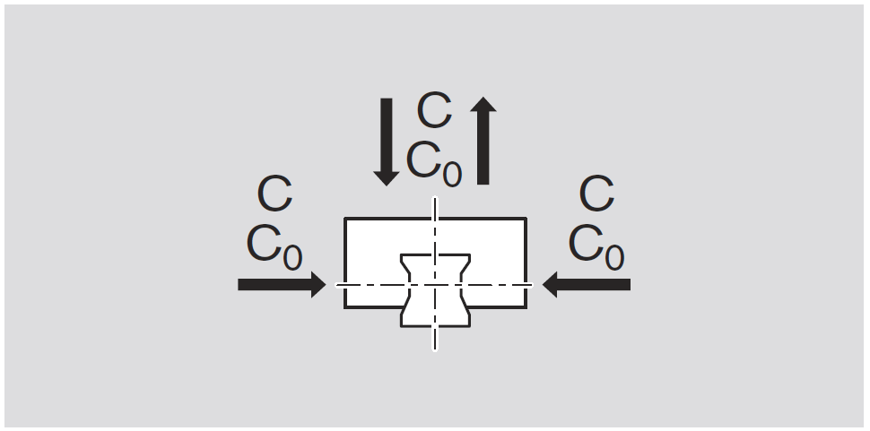 |
| The radial loading of constant magnitude and direction which a linear rolling bearing can the oretically endure for a nominal life of 105 meters distance traveled (as per ISO 14728 Part 1). |
Static load in the load direction that corresponds to a calculated load in the center of the contact point with the greatest load between the rolling element (ball) and track zone (guide rail) of 4200 MPa. |
Note:
The dynamic load capacities given
in the tables are 20% above the ISO values. These values have been confirmed in tests. |
Note:
With this load on the contact point, a permanent overall deformation of the rolling element and track zone occurs, corresponding to around 0.0001 times the ball diameter (as per ISO 14 728-1). |
| |
|
|
|
| |
|
|
|
| Definition and calculation of the nominal life |
| The calculated service life which an individual linear rolling bearing, or a group of apparently identical rolling element bearings operating under the same conditions, can attain with a 90% probability, with contemporary, commonly used materials and manufacturing quality under conventional operating conditions (as per ISO 14728-1). |
| |
| |
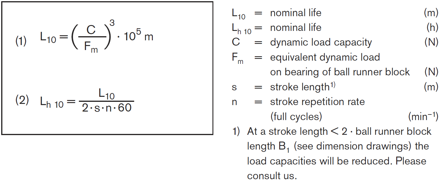
| Nominal life at constant speed |
| If the speed is constant, calculate the nominal life L10 in meters or Lh 10 in hours according to formula (1) or (2). |
 |
| |
| |
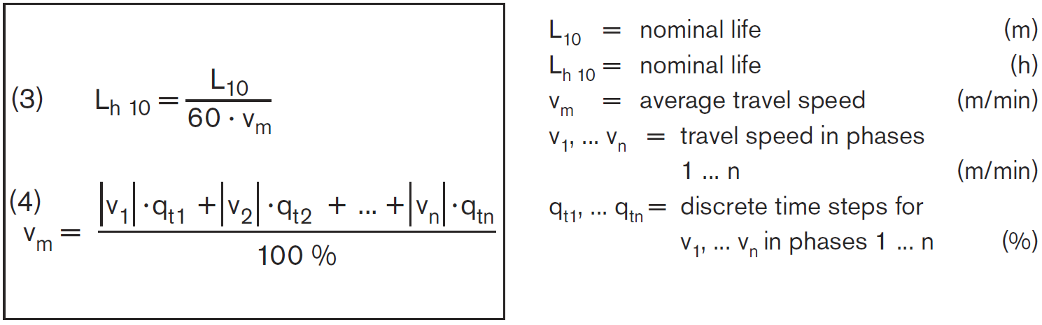
| Nominal life at variable speed |
| If the speed varies, calculate the nominal life Lh 10 in hours according to formula (3) and, if necessary,formula (4). |
 |
| |
| |
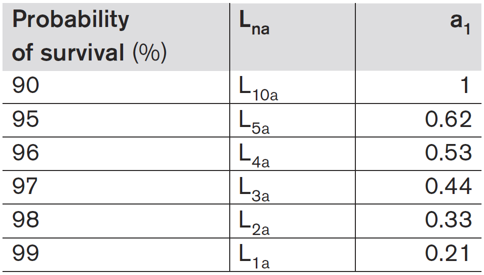
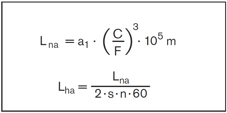
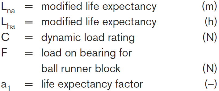
| Modified life expectancy calculation |
| If 90% probability is not sufficient, the nominal life values must be reduced by the factor a1 as given in the table. |
 |
 |
 |
| |
| |
| Equivalent dynamic load on bearing for calculation of service life |
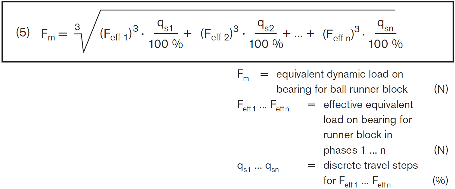
| Equivalent dynamic load with variable load on bearing. |
| If the bearing is subject to variable loads, the equivalent dynamic load Fm must be calculated according to formula (5). |
 |
| |
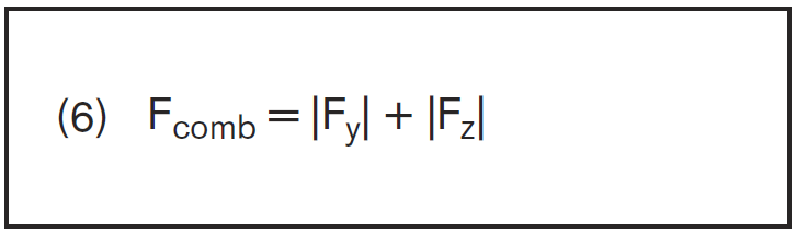
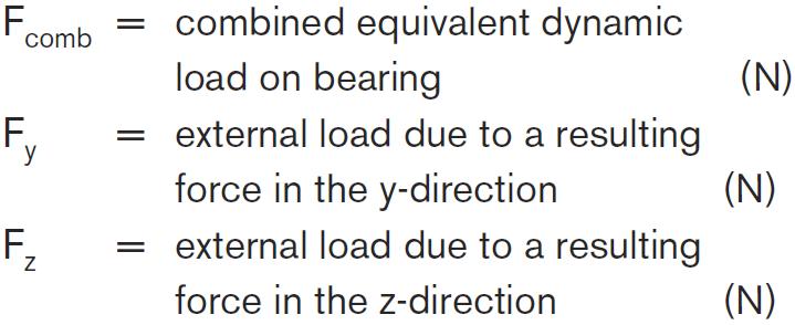
| Equivalent dynamic load with combined load on bearing. |
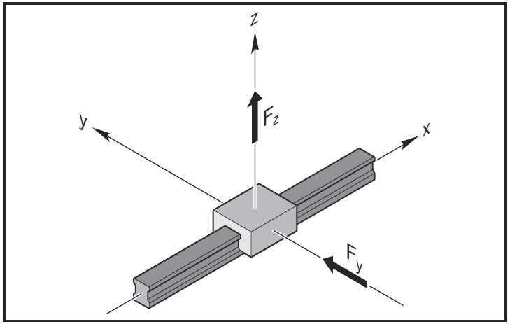
| The dynamic equivalent load on bearing Fcomb resulting from combined vertical and horizontal external loads is calculated according to formula (6). |
|
Note
The structure of the Ball Rail System permits this simplified calculation.
|
|
 |
 |
Note
If Fy and Fz involve different load levels, Fy and Fz must be calculated separately using formula (5). An external load acting at an angle on the ball runner block is to be broken down into its positive and negative Fy and Fz components, and these values are then to be used in formula (6). |
 |
| |
|
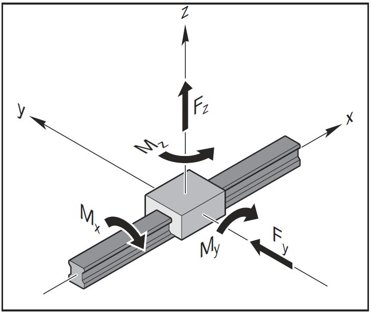
| Equivalent dynamic load with combined load on bearing in conjunction with a torsional and/or longitudinal moment. |
| The combined equivalent load on bearing Fcomb resulting from combined vertical and horizontal external loads in conjunction with a torsional and/or longitudinal moment is calculated according to formula (7). |
Note
Formula (7) applies only when using a single guide rail with a single ball runner block. The formula is simpler for other combinations. |
|
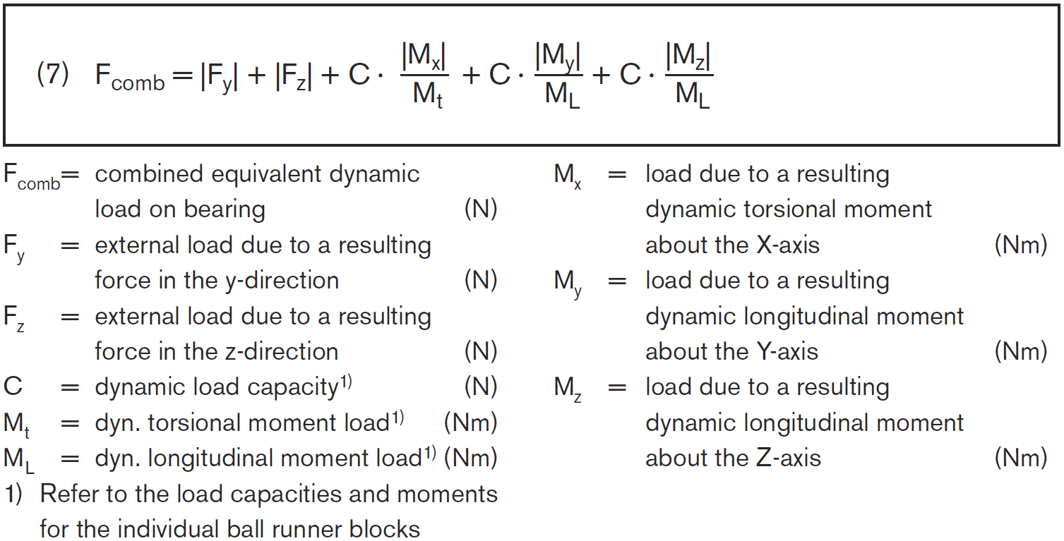 |
Note
If Fy and Fz involve different load levels, Fy and Fz must be calculated separately using formula (5). An external load acting at an angle on the ball runner block is to be broken down into its positive and negative Fy and Fz components, and these values are then to be used in formula (7). |
 |
| |
|
| Equivalent static load on bearing. |
Combined external static load resulting from vertical and horizontal external loads in conjunction with a static torsional and/or longitudinal moment.
Calculate the equivalent static load F0 comb according to formula (10). |
| |
Note
The equivalent static load F0 comb must not exceed the static load capacity C0.
Formula (10) applies only when using a single guide rail with a single ball runner block. The formula is simpler for other combinations. |
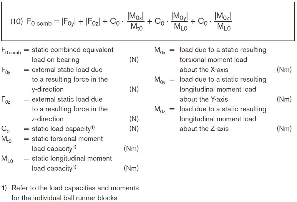 |
Note
An external load acting at an angle on the ball runner block is to be broken down into its positive and negative F0y and F0z components, and these values are then to be used in formula (10). |